
Introduction
Plastic film extrusion is one of the most important processing techniques in the polymer industry. It is widely used for manufacturing packaging films, agricultural films, shrink films, liners, and specialty barrier films. The extrusion process involves converting solid polymer granules into a continuous, homogeneous molten polymer, which is then forced through a die to obtain films of required thickness, width, and properties.
This blog explains the complete film extrusion process, focusing on extruder construction, screw design, mixing systems, materials of construction, operating parameters, and downstream equipment, with suitable examples and tables for better understanding.


1. What is Plastic Film Extrusion?
Extrusion of plastic films consists of converting polymer granules or pellets into a continuous, uniform melt and forcing the melt through a die to produce thin films of various shapes and dimensions.
Basic Principle
- Polymer granules are fed into the extruder.
- Heat and mechanical shear melt the polymer.
- The molten polymer is homogenized.
- The melt is forced through a die.
- The film is cooled, stretched, and wound.
Commonly Extruded Films
- LDPE, HDPE, LLDPE
- PP, PVC
- Specialty films (BOPP, BOPET, nylon)
2. Extruder: Heart of the Film Extrusion Process
An extruder is a machine that melts, mixes, and conveys polymer melt under pressure to the die.
Basic Construction
An extruder mainly consists of:
- Hopper
- Barrel
- Screw
- Heating and cooling system
- Drive system
The extruder is usually a cylindrical barrel inside which a rotating screw conveys the polymer.
3. Size of Extruder
The size of an extruder is defined by its screw diameter.
Example
- 45 mm extruder → small lab or pilot line
- 65–75 mm extruder → medium film line
- 90–120 mm extruder → high-output industrial line
Larger screw diameters result in:
- Higher output
- Higher power consumption
- Greater melt volume
4. Extruder Screw: Design and Geometry
The screw is the most critical component of the extruder. It performs feeding, melting, mixing, and pressurization.
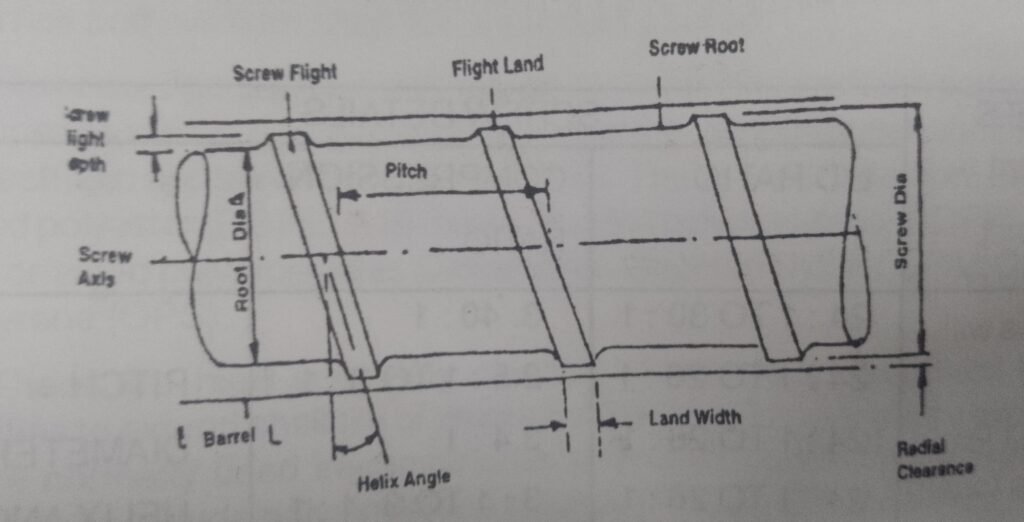
Important Screw Parts
- Screw flight
- Flight land
- Root diameter
- Helix angle
- Pitch
- Flight depth
Key Screw Dimensions
| Parameter | Description |
|---|---|
| Screw Diameter (D) | Outside diameter of the screw |
| Root Diameter | Diameter at the screw core |
| Flight Depth | Difference between screw diameter and root diameter |
| Pitch | Axial distance between two flights |
| Helix Angle | Angle of screw flight |
| Screw Clearance | Gap between screw and barrel |
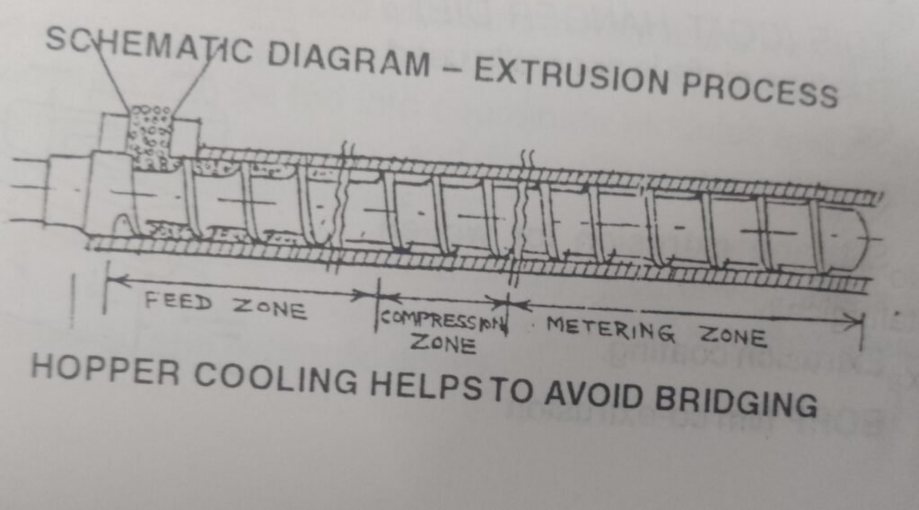
5. Screw Zones in Film Extrusion
A conventional extrusion screw is divided into three zones:
5.1 Feed Zone
- Polymer granules enter the extruder
- Solid conveying occurs
- Channel depth is maximum
- No melting initially
5.2 Compression (Transition) Zone
- Polymer starts melting
- Channel depth decreases
- Pressure builds up
- Air removal begins
5.3 Metering Zone
- Fully molten polymer
- Constant channel depth
- Uniform melt delivery to die
- Pressure stabilization
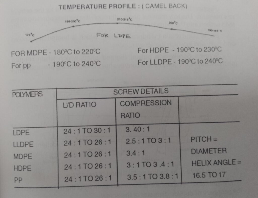
6. Important Screw Design Ratios
6.1 Compression Ratio
Compression Ratio =Metering zone channel depthFeed zone channel depth
- Typical range: 2:1 to 4:1
- Higher ratio → better melting but more shear
- Lower ratio → suitable for heat-sensitive polymers
6.2 L/D Ratio (Length to Diameter Ratio)
L/D Ratio=Screw DiameterScrew Length
| L/D Ratio | Application |
|---|---|
| 20:1 | Basic extrusion |
| 24:1 | Film extrusion |
| 30:1+ | High mixing & output |
7. Mixing Sections in Film Extrusion
To achieve uniform melt quality, special mixing sections are incorporated into screws.
7.1 Maddock Mixing Section
- Separates solid and melt
- Improves distributive mixing
- Reduces unmelted particles
7.2 Mixing Pins and Rings
- Installed on screw or barrel
- Improve homogenization
- Useful for color masterbatch mixing
8. Homogenization of Polymer Melt
Homogenization ensures:
- Uniform temperature
- Uniform viscosity
- No gels or unmelted particles
- Better film clarity and strength
Poor homogenization leads to:
- Thickness variations
- Weak spots
- Surface defects
9. Barrel Design and Grooved Barrels
Grooved Barrels
- Grooves provided in feed section
- Improve solid conveying
- Increase output
- Reduce slippage
Common in:
- HDPE and LLDPE film extrusion
10. Materials of Construction
Extruder components are exposed to:
- High temperature
- High pressure
- Abrasion
- Corrosion
10.1 Barrel Materials
- Nitrided steel (most common)
- Carbide-lined barrels
10.2 Screw Materials
- Alloy steel with surface hardening
- Tungsten carbide coatings
Advanced Materials
Titanium Carbide Composites
- Trade name: FERRO-TIC
- Used for hard-facing
- Excellent abrasion resistance
Cobalt & Nickel Alloys
- Increasingly used
- High wear and corrosion resistance
11. Wear-Resistant Screws and Barrels
Xaloy Technology (USA)
- Developed by Xaloy Pulaski, USA
- Metallurgical bonding of tungsten carbide
Advantages
- No abrasion screw
- Long service life
- Superior corrosion resistance
Xaloy-800 Barrel
- Tungsten carbide bonded barrel
- Excellent for abrasive polymers
- Used in high-output film extrusion
12. Heating and Cooling Systems
Heating System
- Electrical resistance heaters
- Multiple temperature zones
- PID temperature control
Cooling System
- Air cooling fans
- Water cooling channels
- Prevents polymer degradation
13. Breaker Plate and Screen Pack
Breaker Plate
- Thick metal plate with holes
- Supports screen pack
- Converts rotational flow to linear flow
Screen Pack
- Fine mesh screens
- Filters contaminants
- Builds back pressure
| Function | Benefit |
|---|---|
| Filtration | Clean melt |
| Pressure buildup | Better mixing |
| Flow uniformity | Defect-free film |
14. Downstream Equipment in Film Extrusion
After exiting the die, the molten film passes through several downstream units.
Common Downstream Equipment
- Die (flat or annular)
- Air ring (blown film)
- Chill rolls (cast film)
- Nip rolls
- Thickness gauge
- Corona treater
- Winder
15. Example: LDPE Blown Film Extrusion Line
- LDPE granules fed into hopper
- Screw melts and homogenizes polymer
- Melt passes through breaker plate and screen
- Annular die forms tubular melt
- Air blown to form bubble
- Bubble cooled by air ring
- Film collapsed and wound
16. Advantages of Proper Extruder Design
- Uniform film thickness
- Higher output
- Reduced energy consumption
- Longer equipment life
- Better mechanical properties
17. Common Problems and Solutions
| Problem | Cause | Solution |
|---|---|---|
| Melt fracture | High shear | Reduce screw speed |
| Gels | Poor melting | Use mixing section |
| Thickness variation | Poor homogenization | Improve screw design |
| Excess wear | Abrasive fillers | Use carbide-lined barrel |
Conclusion
Plastic film extrusion is a complex but well-controlled process that depends heavily on extruder design, screw geometry, mixing efficiency, and material selection. Advances such as grooved barrels, Maddock mixers, FERRO-TIC coatings, and Xaloy tungsten carbide systems have significantly improved productivity, quality, and equipment life.
A thorough understanding of extruder components, screw zones, ratios, and downstream equipment is essential for producing high-quality plastic films efficiently and economically.