Introduction
Injection moulding is one of the most widely used manufacturing processes for producing plastic components with high precision, repeatability, and efficiency. Products such as bottle caps, automotive parts, medical disposables, electronic housings, and household goods are commonly manufactured using injection moulding machines.
Injection moulding machines can be classified in several ways, but the most common and important classification is based on:
- Type of clamping unit (locking unit)
- Type of injection unit
The clamping unit holds the mould closed under high pressure during injection, while the injection unit melts and injects the plastic material into the mould cavity. This article provides a detailed explanation of both units, their types, working principles, advantages, disadvantages, along with tables, examples, and industry statistics.
Basic Structure of an Injection Moulding Machine
An injection moulding machine consists of three major sections:
- Injection Unit – Melts and injects plastic into the mould
- Clamping Unit (Locking Unit) – Holds the mould closed during injection
- Control System & Power Unit – Controls pressure, temperature, speed, and timing
Among these, clamping and injection units determine machine performance and application suitability.
Classification Based on Clamping Unit (Locking Unit)
The clamping unit is responsible for closing, opening, and holding the mould firmly against the high injection pressure. Many types of locking units have been devised, but most can be classified into two main categories:
- Direct Hydraulic Locking Systems
- Toggle Locking Systems
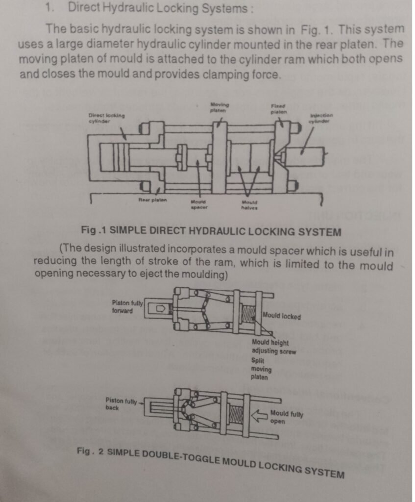
1. Direct Hydraulic Locking Systems
Description
In a direct hydraulic locking system, the clamping force is generated directly by hydraulic cylinders acting on the moving platen. Hydraulic oil pressure pushes the ram forward, closing the mould and maintaining the required clamping force.
There is no mechanical amplification as seen in toggle systems—the force applied is directly proportional to hydraulic pressure and piston area.
Working Principle
- Hydraulic oil is pumped into the cylinder
- The ram moves forward, closing the mould
- Pressure is maintained to hold the mould closed
- After cooling, oil is released and the mould opens
The ram speed can be controlled precisely by varying the oil flow rate.
Advantages of Direct Hydraulic Locking Systems
- Self-lubricating cylinder
- Hydraulic oil lubricates internal parts, reducing friction
- Few moving parts
- Lower mechanical complexity compared to toggle systems
- Easy accommodation of mould height variations
- Suitable for frequent mould changes
- Smooth and controlled ram movement
- Ram speed is easily adjusted by controlling oil flow
- Uniform clamping force
- Ideal for large and thick-walled moulds
Disadvantages of Direct Hydraulic Locking Systems
- High power consumption
- Large volumes of pressurised oil must be moved
- Energy inefficiency
- Oil circulation continues even when full clamping force is reached
- Heat generation
- Excess oil flow produces heat, requiring cooling systems
- Slower response compared to toggle systems
- Especially in high-speed production environments
Applications of Direct Hydraulic Locking Systems
- Large plastic containers
- Automotive bumpers
- Industrial crates
- Thick-walled products
- Low-cycle, high-force applications
2. Toggle Locking Systems
Description
A toggle system uses a mechanical linkage arrangement (toggle bars) to multiply force. A small hydraulic cylinder operates the toggle mechanism, which generates very high clamping force when the toggle bars move into a straight-line (locked) position.
Working Principle
- Hydraulic cylinder initiates mould closing
- Toggle links move rapidly at first (fast closing)
- As toggle bars approach alignment, speed decreases
- Near full lock, very high clamping force is generated
- Only a small holding force is required to maintain lock
This gradual slowdown protects mould surfaces from damage.
Advantages of Toggle Locking Systems
- Rapid mould closing
- High productivity and shorter cycle times
- Energy efficiency
- Minimal hydraulic pressure required once locked
- High clamping force with small cylinder
- Mechanical advantage of toggle mechanism
- Reduced oil circulation
- Lower power consumption
- Ideal for high-speed mass production
Disadvantages of Toggle Locking Systems
- Greater wear and tear
- Many moving mechanical parts
- Precise mould height setting required
- Incorrect setup can cause mould damage
- Higher maintenance
- Toggle joints, pins, and bearings require regular inspection
- Less flexible for frequent mould changes
Applications of Toggle Locking Systems
- Thin-walled packaging
- Bottle caps and closures
- Medical disposables
- Consumer electronics housings
- High-volume production lines
Comparison Between Direct Hydraulic and Toggle Clamping Systems
| Feature | Direct Hydraulic System | Toggle System |
|---|---|---|
| Clamping force generation | Direct hydraulic pressure | Mechanical amplification |
| Energy efficiency | Lower | Higher |
| Mould height adjustment | Easy | Requires precision |
| Number of moving parts | Few | Many |
| Maintenance | Low | Higher |
| Cycle speed | Moderate | High |
| Best suited for | Large, thick parts | High-speed mass production |
Classification Based on Injection Unit
The injection unit melts plastic material and injects it into the mould cavity. Over time, several injection unit designs have evolved to improve mixing, melting efficiency, and shot accuracy.
The main types of injection units are:
- Conventional Injection Unit
- Piston Type Injection Unit
- Screw Type Preplasticating Injection Unit
- Reciprocating Screw Injection Unit
1. Conventional Injection Unit
Description
This is the earliest form of injection unit where plastic material is melted in a heated barrel and injected using a plunger or ram.
Features
- Simple construction
- Limited plasticizing efficiency
- Poor temperature uniformity
Applications
- Thermosetting plastics
- Low-precision moulding
2. Piston Type Injection Unit
Description
In the piston type unit, plastic granules are heated in the barrel and injected using a hydraulic piston.
Advantages
- Simple and rugged design
- Suitable for thermosetting plastics
Disadvantages
- Poor mixing of molten plastic
- High temperature gradients
- Inconsistent shot quality
Example
Early phenolic and urea moulding machines commonly used piston-type injection units.
3. Screw Type Preplasticating Injection Unit
Description
This system uses a rotating screw to melt and mix the plastic material. The molten plastic is stored in a separate chamber and injected using a piston.
Advantages
- Improved plasticizing and mixing
- Better temperature control
- Reduced material degradation
Disadvantages
- More complex design
- Higher cost
Applications
- Engineering plastics
- Medium-precision components
4. Reciprocating Screw Injection Unit
Description
The reciprocating screw injection unit is the most widely used system today. The screw performs two functions:
- Rotates to melt and mix plastic
- Moves forward axially to inject molten plastic
Advantages
- Excellent melting and mixing
- Accurate shot size control
- Uniform temperature distribution
- Suitable for almost all thermoplastics
Industry Usage Statistics
- Over 85% of modern injection moulding machines use reciprocating screw systems
- Improves part consistency by 20–30% compared to piston systems
- Reduces material waste by 15–25%
Applications
- Automotive components
- Medical devices
- Consumer goods
- Precision engineering parts
Comparison of Injection Unit Types
| Injection Unit Type | Plasticizing Quality | Complexity | Current Usage |
|---|---|---|---|
| Conventional | Poor | Low | Obsolete |
| Piston Type | Moderate | Low | Limited |
| Screw Preplasticating | Good | Medium | Moderate |
| Reciprocating Screw | Excellent | High | Very High |
Conclusion
Injection moulding machines are primarily classified based on clamping units and injection units, both of which play a critical role in machine performance and product quality.
- Direct hydraulic locking systems are robust, flexible, and suitable for large moulds but consume more power.
- Toggle locking systems offer high speed and energy efficiency, making them ideal for mass production.
- Among injection units, the reciprocating screw injection unit dominates modern manufacturing due to its superior plasticizing efficiency and precision.
Understanding these classifications helps manufacturers select the right machine for productivity, quality, and cost efficiency, making injection moulding one of the most reliable processes in the plastics industry.
About Me
I am sujith, passionate about manufacturing engineering and plastic processing technologies, with a strong interest in injection moulding, polymer processing, and industrial production systems. Through this blog, I aim to simplify complex engineering concepts into clear, practical, and exam-oriented explanations for students, technicians, and industry professionals.
My content focuses on:
- Injection moulding processes and machinery
- Plastic manufacturing techniques
- Industrial engineering fundamentals
- Practical examples, tables, and real-world applications
This platform is created to help engineering students, diploma holders, and professionals gain a strong conceptual understanding and stay connected with real manufacturing practices.