Introduction
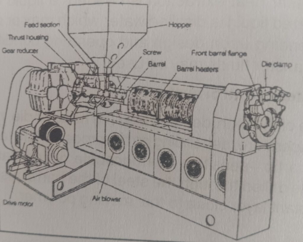
The single screw extruder is one of the most widely used machines in the plastics and polymer processing industry. It plays a crucial role in converting raw polymer materials into finished or semi-finished products such as films, pipes, sheets, profiles, and pellets. Despite its simple appearance, the single screw extruder is a highly engineered system that combines mechanical strength, thermal control, and precise material handling.
This blog explains the design fundamentals of a single screw extruder, focusing on:
- Barrel dimensions (D and L/D ratio)
- Feed section and feeding mechanism
- Barrel pressure tolerance
- Heat input and extraction mechanisms
- Temperature control systems
- Screw design
- Gearbox, thrust bearing, and drive systems
Real-world examples, engineering concepts, and a summary table are included to improve understanding.


1. Basic Dimensions of a Single Screw Extruder
A single screw extruder is primarily defined by two dimensional parameters:
1.1 Bore Diameter (D)
The bore diameter (D) is the internal diameter of the barrel in which the screw rotates. It determines:
- Throughput capacity
- Power requirement
- Size of the extruder
Typical bore diameters range from:
- 20 mm (laboratory extruders)
- 150–200 mm (industrial production lines)
Larger diameters allow higher output but require stronger materials and higher torque drives.
1.2 Length-to-Diameter Ratio (L/D Ratio)
The L/D ratio is the ratio of the effective barrel length (L) to the bore diameter (D).L/D=Bore DiameterBarrel Length
Common L/D ratios include:
- 20:1 – simple extrusion
- 24:1 to 30:1 – general-purpose extrusion
- 32:1 to 40:1 – high output and better melting
A higher L/D ratio provides:
- Better melting
- Improved mixing
- Stable pressure development
Example
If an extruder has:
- Bore diameter = 60 mm
- Barrel length = 1800 mm
L/D=601800=30
This is a 30:1 extruder, commonly used for blown film and pipe extrusion.
2. Extruder Barrel Design
2.1 Function of the Barrel
The barrel is a stationary cylindrical component that:
- Houses the rotating screw
- Contains the molten polymer
- Transfers heat to or from the material
- Withstands very high internal pressures
2.2 Pressure Tolerance Requirement
The barrel must tolerate internal pressures up to 10,000 psi (≈ 70 MPa) without exceeding 0.15% elastic strain.
This requirement ensures:
- No permanent deformation
- Accurate screw-barrel clearance
- Long service life
- Stable extrusion output
To meet this condition, barrels are typically made from:
- Nitrided alloy steel
- Bimetallic liners
- Hardened tool steels
Why 0.15% Strain Limit?
Beyond 0.15% strain:
- Material may enter plastic deformation
- Barrel bore may expand permanently
- Screw wear and melt leakage increase
Hence, elastic behavior is strictly maintained.
3. Feed Section of the Extruder
3.1 Feed Opening and Hopper
At the feed end of the barrel, there is an opening into the barrel bore through which raw material enters. This opening is usually connected to a hopper.
Key characteristics:
- Often made as a separate casting
- Bolted or clamped to the barrel
- Designed for easy material flow
Raw materials may include:
- Polymer granules
- Powder
- Regrind
- Additives
3.2 Feed Throat Cooling
The feed section is usually jacketed for room-temperature water cooling.
Purpose of Cooling
- Prevent premature melting of polymer
- Avoid material sticking or bridging
- Ensure smooth feeding into the screw flights
If polymer melts too early:
- Feeding becomes inconsistent
- Screw may starve
- Output becomes unstable
Example
In LDPE film extrusion, improper feed throat cooling can cause:
- Melt sticking in hopper
- Reduced output
- Frequent shutdowns
4. Barrel Heat Input and Heat Extraction Mechanisms
4.1 Heat Input Mechanisms
Heat is added to the barrel using:
- Electrical resistance heaters
- Band heaters
- Ceramic heaters
These heaters are mounted in zones along the barrel length.
Functions:
- Assist in polymer melting
- Maintain desired melt temperature
- Compensate for heat loss
4.2 Heat Extraction Mechanisms
Heat extraction is equally important to prevent overheating.
Common cooling methods:
- Air cooling (fans or blowers)
- Water cooling channels
- Oil cooling (high-temperature systems)
Cooling helps:
- Maintain temperature stability
- Prevent polymer degradation
- Control melt viscosity
Heat Balance Concept
The barrel temperature depends on:
- Heater input
- Cooling removal
- Heat generated by shear in the screw
An optimal balance ensures:
- Uniform melt
- Stable pressure
- Consistent product quality
5. Barrel Temperature Control System
Each barrel zone has an independent temperature control system, consisting of:
- Thermocouples
- PID temperature controllers
- Heaters and cooling devices
Typical Temperature Profile
- Feed zone: Lower temperature
- Compression zone: Moderate temperature
- Metering zone: Highest temperature
Benefits of Zoned Control
- Precise melt control
- Reduced thermal degradation
- Improved dimensional accuracy of product
6. Screw of a Single Screw Extruder
6.1 Function of the Screw
The screw is the heart of the extruder. Its main functions are:
- Conveying material
- Melting polymer
- Mixing additives
- Building pressure
6.2 Screw Geometry
A standard screw consists of three sections:
- Feed section
- Compression (transition) section
- Metering section
Key screw parameters:
- Flight depth
- Channel width
- Compression ratio
- Helix angle
Example
A screw with a compression ratio of 3:1 is suitable for:
- LDPE
- LLDPE
- HDPE
Higher ratios are used for rigid polymers.
7. Gearbox and Thrust Bearing
7.1 Gearbox
The gearbox:
- Reduces motor speed
- Increases torque
- Transfers power to the screw
Extruders require:
- High torque at low speeds
- Continuous duty performance
Gearboxes are typically:
- Helical or planetary type
- Oil-lubricated
- Designed for shock loads
7.2 Thrust Bearing
During extrusion, the screw experiences axial thrust due to melt pressure.
The thrust bearing:
- Absorbs axial loads
- Prevents screw movement
- Protects gearbox and motor
High-capacity roller or tilting-pad thrust bearings are commonly used.
8. Drive System of the Extruder
8.1 Drive Motor
Modern extruders use:
- AC induction motors
- DC motors
- Servo motors (high precision)
The motor provides:
- Rotational motion
- Speed control
- Torque stability
8.2 Speed Control
Speed is controlled using:
- Variable Frequency Drives (VFDs)
- Thyristor controllers (DC drives)
Benefits:
- Adjustable output rate
- Better process control
- Energy efficiency
9. Summary Table: Major Components of a Single Screw Extruder
| Component | Function | Key Features |
|---|---|---|
| Barrel | Houses screw, contains melt | High pressure resistance (10,000 psi) |
| Bore Diameter (D) | Determines capacity | Larger D = higher output |
| L/D Ratio | Determines melting efficiency | Common range 20–40 |
| Feed Section | Material entry | Water-cooled to prevent melting |
| Heating System | Adds thermal energy | Band or ceramic heaters |
| Cooling System | Removes excess heat | Air or water cooling |
| Screw | Conveys and melts polymer | Three-zone design |
| Gearbox | Torque transmission | High torque, low speed |
| Thrust Bearing | Absorbs axial load | Prevents screw movement |
| Drive Motor | Powers screw | Variable speed control |
Conclusion
The single screw extruder is a carefully balanced system where mechanical strength, thermal control, and material flow must work together seamlessly. From the barrel’s ability to withstand 10,000 psi pressure, to the feed throat cooling, heat input and extraction mechanisms, and precision screw drive systems, every component plays a vital role in producing consistent, high-quality plastic products.
Understanding these fundamentals is essential for:
- Polymer engineering students
- Process engineers
- Extrusion machine operators
- Product designers
A well-designed and properly controlled extruder ensures high productivity, energy efficiency, and long equipment life.